Finalizing the electrical design
After testing the different sensors, the Raspberry Pi connection via USB, the Light Module and more we are finishing the electrical design... Atleast for now ;)
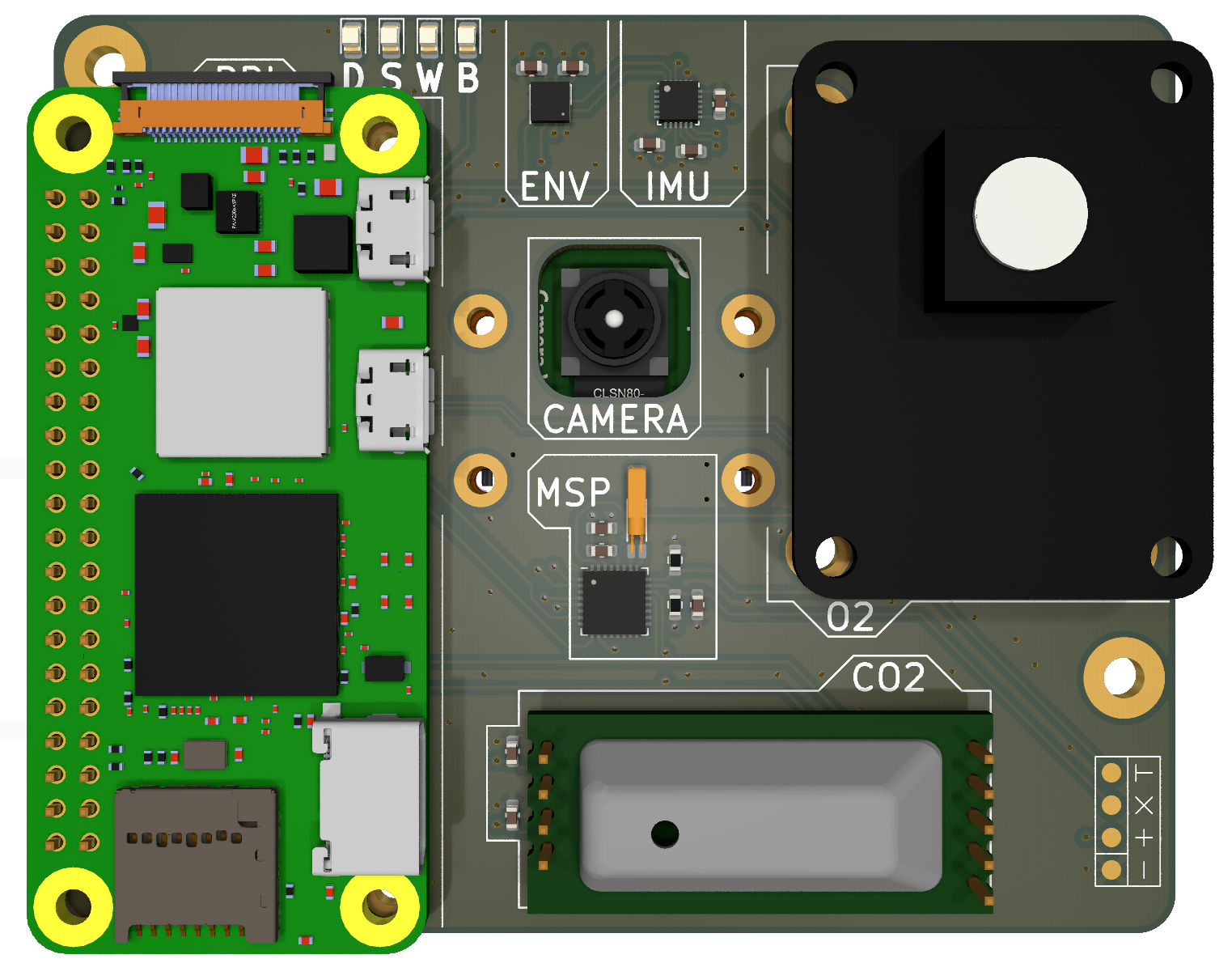
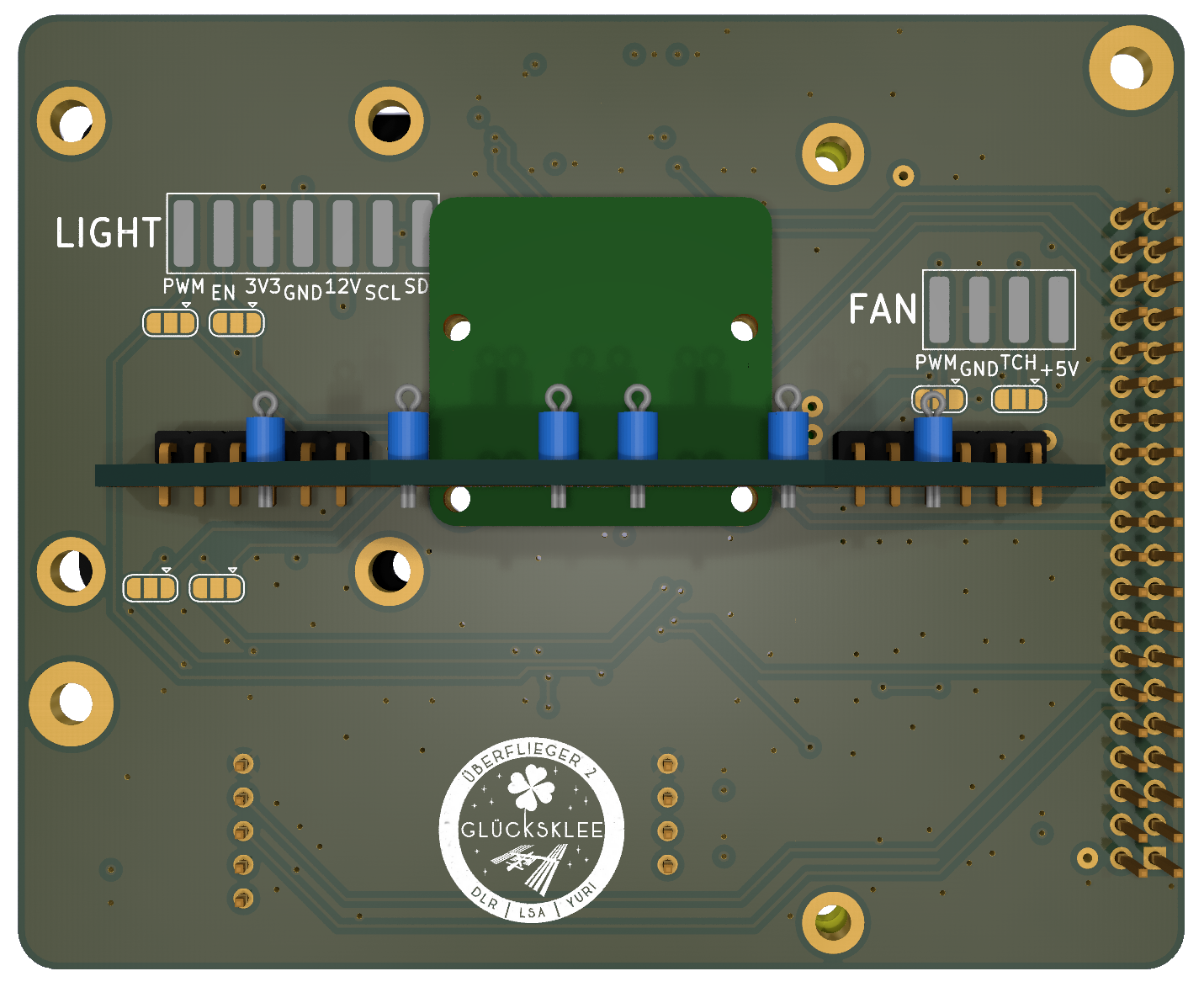
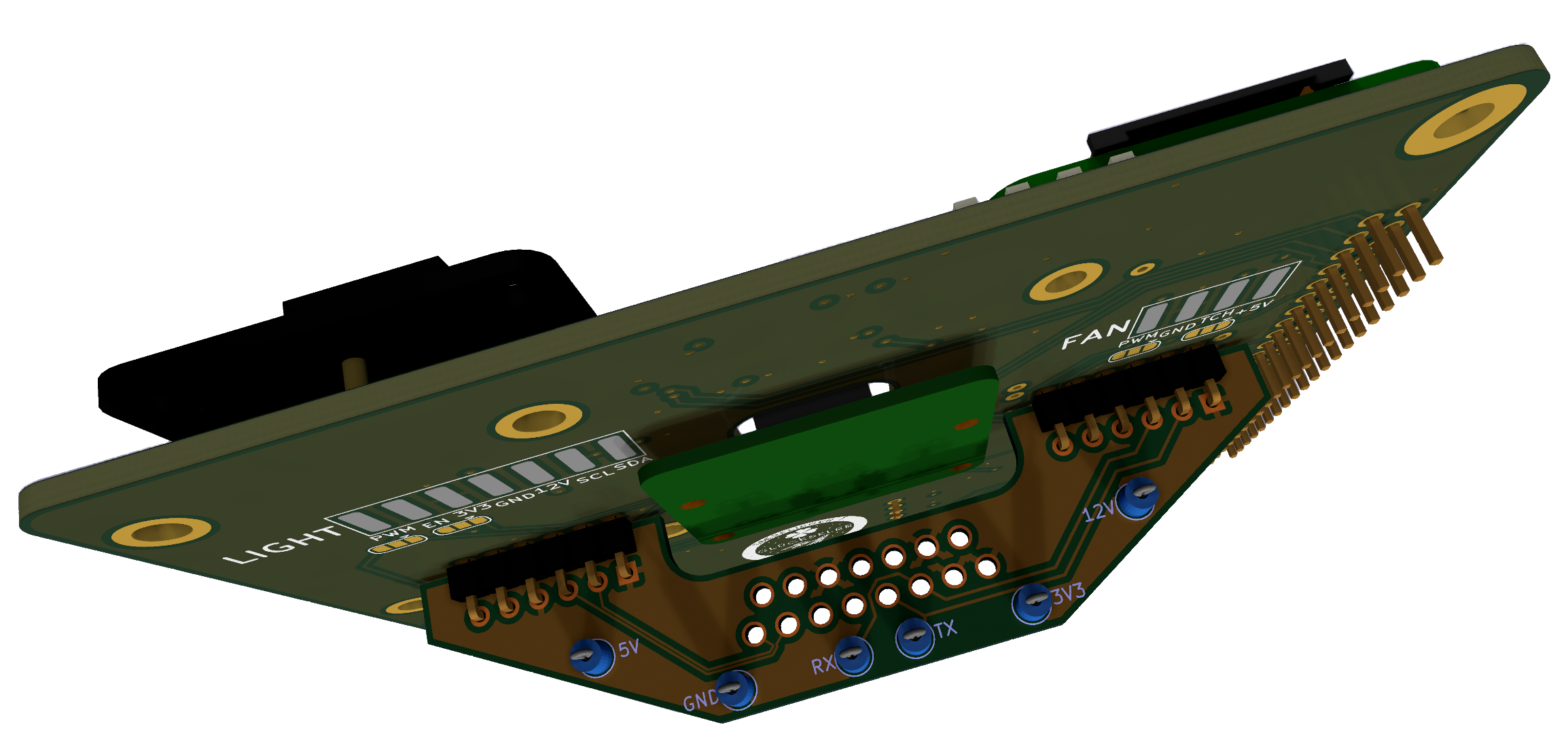
The first Mainboard prototype has shown, that even with few components the routing of the wires can be pretty annoying. Thats why we switch to a four-layer PCB design. The front contains most of the components: The Raspberry Pi Zweo 2W, a CO2 and a O2 sensor, a environmental sensor that can measure humidity, pressure and temperature and an additional mixed-signal processor (MSP), a MSP430 from Texas Instruments. The camera is placed behind the mainboard and looks through an opening in the center. The addional MSP can be used to outsource the generation of PWM signals of the Raspberry Pi. It also is used as a watchdog. In normal operation, the Raspberry Pi sends a periodic heartbeard the the MSP. If an software-error occurs that leads to stop, the MSP can reset the Raspberry Pi an reboot it. The Backside mainly contains to solder connections to the Light Module and the integrated fan. To connect the Mainboard to the D-Sub connector on the CubeLab, an additional PCB is mounted on the back of the Motherboard. 15 wires run from the D-Sub connector to this four-layer PCB. It has additional probe hooks to measure volatage stability during testing.


